Skip to content

My friend and colleague Doug Brooks has decided to take retirement. Therefore he has summarized his best articles and parts of his books in a new work "UltraCAD's Best".
Doug Brooks: UltraCAD's Best

Also, his calculation tools are now available for FREE instead of $250:
FREE: UltraCAD tools and calculators

Let's wish Doug lots of good times with his (big) family!

TRM3.5.7 was released on 10.11.2021. At first glance, the differences seem to be small. But TRM has become much more performant for very large or high resolution boards (> 10 megapixels per layer, many layers or tens of thousands of laser vias). Also, once again some dialects in the input files are better interpreted.
You may request a test installation here

Doug Brooks has revised his previously self-distributed book on Amazon and it is now available from Artech House.

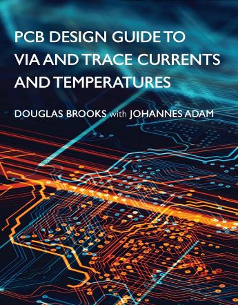
PCB Design Guide to Via and Trace Currents and Temperatures

Explores how hot traces and vias will be and what board, circuit, design, and environmental parameters are the most important;
● Covers PCB materials (copper and dielectrics) and the role they play in the heating and cooling of traces;
● Details the IPC curves found in IPC 2152, the equations that fit those curves and computer simulations that fit those curves and equations;
● Presents sensitivity analyses that show what happens when environments are varied, including adjacent traces and planes, changing trace lengths, and thermal gradients;
● Explores via temperatures and what determines them, along with fusing issues and whether we can predict the fusing time of traces;
● Readers learn how to measure the thermal conductivity of dielectrics and how to measure the resistivity of copper traces and why many prior attempts to do so have been doomed to failure.

He also uses TRM and outlines the process of model building.

https://us.artechhouse.com/PCB-Design-Guide-to-Via-and-Trace-Currents-and-Temperatures-P2191.aspx

Textbook in coorperation with Doug Brooks "PCB Design Guide to Via Trace Currents and Temperatures"

You may also be interested in other titles from the Artech range.

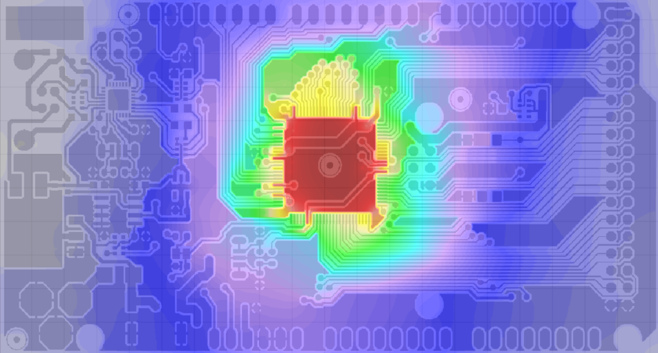
The thermal resistance "Junction-Ambient" ΘJA or RΘJA links a temperature node inside the silicon die (Junction) with the surrounding air (Ambient). "Ambient" includes everything around the component, from the pad to the air - i.e. especially the special topology of the PCB. Therefore RΘJA cannot be used to predict the temperature for a specific board. Here are some screenshots from Don't believe the data sheets. Design007 Magazine (September 2020).They show that the heat spreading on a real PCB is not perfect and that it was certainly different on the test PCB of the data sheet.

  • This Arduino board is 2-layer. The parallel running tracks can improve and impede the heat spreading.
Simulated thermal image of top Layer of Arduino Board
Top Layer of an Arduino Board calculated with TRM3


  • Even with multilayer boards with solid inner layers, the layout can dominate the heat spreading. In this evaluation board we see that the thermal vias are in fact useless, because they are just as warm as the component, so no heat    is removed.
PCB Simulation of Microchip Eval Board EVB-USB580X
Bottom Layer of MicroChip Eval Board EVB-USB580X calculated with TRM3

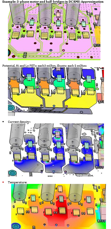
A TRM release is available: assign a resistor attribute (mOhm) to SMD parts to connect nets or copper geometries. Can be applied it with or without net list. The current goes through it and the voltage drop is adapted to the input value. I^2*R can be used for the heat and add to the Joule heat in traces. Also works in temperature-dependet mode.

  • Simple example with resistors. Total resistance is 1 Ohm in each circuit.
  • 3 half-bridges (Rdson=3 mOhm each, yellow)  with shunt resistors (5 mOhm each, green) share the current.

There are several methods for testing for the COVID-19 virus. A cost effective and fast method is real-time fluorescence analysis (RT-LAMP). More details: Vienna Corona Team

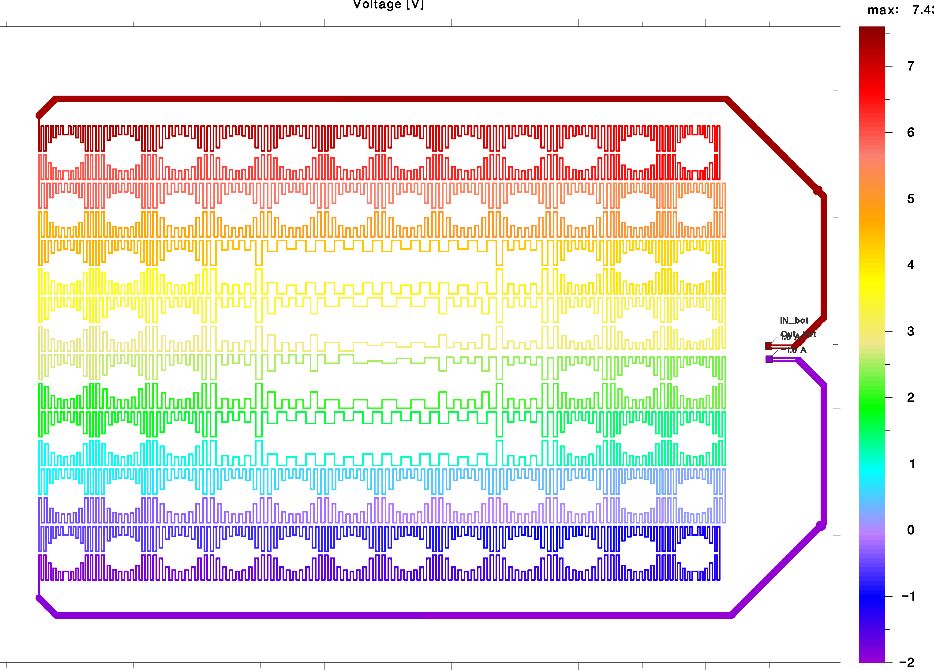
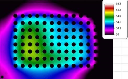
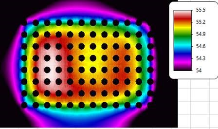
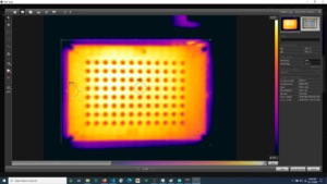
For the a defined reaction of the substrates, all samples in the carrier must be kept at the same temperature. ADAM Research participates voluntarily in the Miriam project by calculating and optimizing the voltage drop in the necessary heating loops and the resulting temperature. In the pilot calculation the heating coil is 18 meters long in a top and bottom part. TRM3 needs only a few seconds for the current density. The geometry comes from an EAGLE design and derived Gerber files. A 1 mm aluminium plate between the top and bottom heating coils has a more uneven temperature distribution than a 2 mm thick plate. The asymmetric distribution is measured qualitatively exactly the same. The aim is to become even more homogeneous and to determine the suitable materials for the next prototypes.

Voltage drop in an 18 m coil
Calculated voltage drop in the coil
TRM3 simulation for Miriam Project
Simulated Trace Heating on 2 mm Aluminum Plate
TRM3 und Miriam Projekt
Simulated Trace Heating on 1 mm Aluminum Plate with TRM3
TRM3 und Miriam Projekt
Infrared image with 1.6 mm Aluminum Prototype


More data! Now netlists with their pads/pins can also be imported from other CAD systems, e.g. from Cadence (Allegro, Orcad), Mentor (Pads, Expedition), Zuken (Cadstar, CR8000), Eagle, Pulsonix, KiCad etc. You only have to export the IPC-D-356 file. This makes it much easier to investigate the current carrying capacity of high current applications.

  • Import ipc file: creates a table with all the nets and pads found.
  • Add Ampere values: either manually or via a .csv file, which could also come from an xls calculation.
  • Calculate how the current heats the traces. Of course also transient.

Altium users will still prefer the script. But there have been small updates as well.

More color! The imported Gerber files are no longer just black and white plots, making it difficult to distinguish layers, but are now displayed in color. This results in a fantastic depth effect in the 3D representation, which helps enormously to control the inputs and to understand the results better and to communicate them to colleagues.

Convince yourself: There is a collection of new videos on YouTube


After almost 2 years of development the new TRM3 is now available as beta roll-out! More elegant and faster than TRM2.

  • Altium Import fully automatic or semi-manual. Almost only 2 clicks.
  • Scripting for Altium Designer 20 enhanced.
  • Input and 3D view of the assembly integrated.
  • 3D mesh reconstruction.
  • Faster Gerber and Excellon Import.
  • Faster calculation of the potential (voltage drop) and current density.
  • Inductance matrix of the nets based on 3D current flow
  • Heat flux vectors.
  • Table of Joule heat per layer and mesh.
  • Table of the heat flow balance per component.
  • FLIR color bar.
  • Result view also 3D.
  • Video with Altium Designer

Request a test installation.

Are you looking for external support?

Europe:
We recommend Cieluch Consulting Engineers for works with Altium, Eagle and Cadence. Also with on-site for layout, circuit design and library services.

US, Canada, Mexico:
We recommend Ulisses Castro (Electronic Engineering M.Sc.) (Hardware, Advance Printed Circuit Board Engineering, Signal, Power and Thermal Integrity). Also in combination with TRM.