Skip to content

Blog

  • Export and Import from Zuken eCADSTAR . A new  Wizard!
    • From schematics
    • From Constraint Browser

eCADSTAR Design & TRM3.9 result

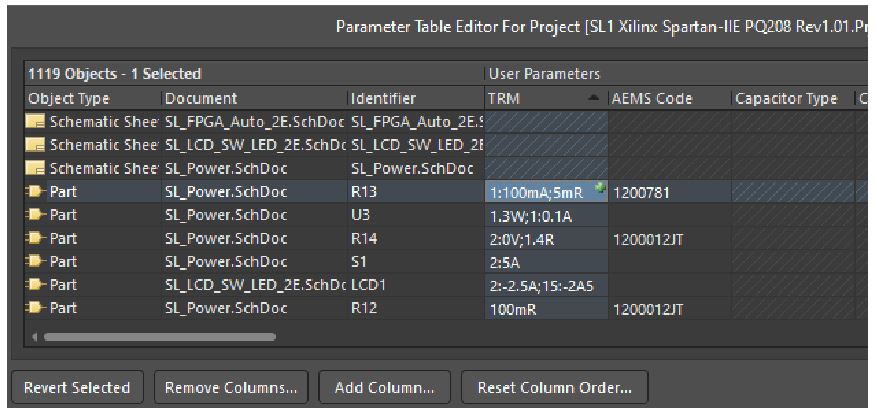
  • Altium Wizard.  Extended  TRM parameter by Amp/Volt and  Ohm for Components
    • From schematics
    • From Parameter Manager

  • Laods
     Prefix for Ohm , like 3mR or 10kR
  • Test it
     Table for power factor (derating) of components


NEW! Interfaces for ZUKEN eCADSTAR 2024 and TRM3

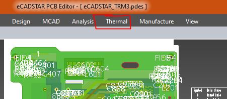
  • Export all relevant design files (+ extras) from e-CADSTAR at the touch of a button
  • Assign thermally relevant parameters (Watts, Amperes, Rth, ...) in schematic or in Constraint Manager of e-CADSTAR
  • Import all data and model setup in TRM3 via 1-button wizard
  • Lots of freedom in modifying the layer structure and other values and parameters in TRM3
  • More about: Zuken eCADSTAR website

Test it yourself. Just ask your ZUKEN reseller, CSK or ADAM-Research for licenses and test installation. Or contact your local Zuken office or reseller.

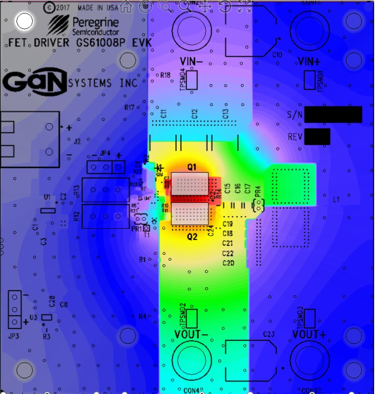
NEW: Interfacing ZUKEN eCADSTAR with TRM3 thermal simulator. Thermal power from components and Amps from traces are converted into to Celsius
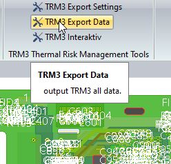
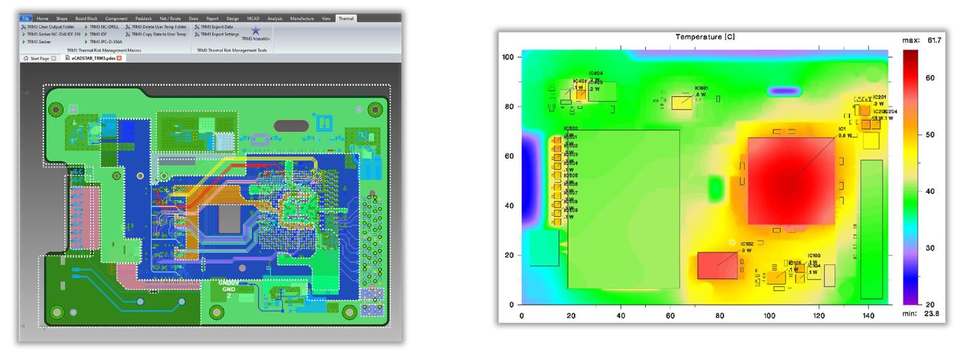
One cklick button to export all design data and parameters from ZUKEN eCADSTAR for a thermal simulation
Plot of simulated temperature in TOP layer. Generated from ZUKEN eCADSTAR data.

In Bodo’s Power Magazine ist mir in einem Beitrag von ROHM’s Trevis Moench sofort ein Bild aufgefallen welches einen Widerstand in breitseitigem und in schmalseitigem Anschluss an die Leiterbahnen zeigt. Wieviel bringt das Drehen des Widerstands für das Thermal Management wirklich für die Temperatur und was ist der Beitrag der Leiterbahn? Darüber wird in einem neuen WhitePaper #14   aufgeklärt. Ich habe gestaunt.

Rohm Shunt Resistor in thermal simulation
Rohm shunt resistor. Shape and direction eventually matter.

Doug Brooks: "Stop thinking about current density!"

January 17, 2024 19:00 to 20:00 CET 1:00 pm-2:00 pm EST

sign up here: Register

TRM continues to evolve. Release number 3.8 is now available

  • More variables for batch mode
  • Export script for Cadence Allegro and Orcad
  • Import Wizard for Cadence
  • More thermal parameters in the Altium schematic
  • Derating table for components

To request a test installation, please go to Request form


Thermo-Electric Circuit Board Simulation with

TRM3.7

Components and currents heat the PCB (assembly) - but how hot will it get? Are the temperature limits complied with? No data sheet or guideline will tell you.

With TRM (Thermal Risk Management) you are able to calculate the thermal performance of your circuit board before the laboratory test

… and with new TRM 3.7 it's even easier to generate a better temperature forecast. Made easier than with add-ons of the big EDA vendors.

• Import your Gerber, placement, drill files or netlist or set the necessary    data manually (see FAQ)

• 3D circuit board model with up to 50 layers

Update: Easy export and import for ALTIUM users

NEW:       Easy export and import for EAGLE users

• Clearly arranged operation

• Templates and file formats for parameter input

• Can also be used without CAD data - for technologists

• No FEM knowledge required

________________________________________

• Accuracy through physics and geometry

• Heating by components and/or currents

• Environmental conditions. Air cooling, heat sinks and heat sinks, radiation into a vacuum, and much more

• Virtual thermograms of all layers and prepregs in high resolution

• DC potential distribution and current density in nets

• Steady-state or transient

• Temperature-dependent material data

• Self and mutual inductance (inductance matrix)

• Automatically generated result tables

________________________________________

• Licensing by your server

• Short to moderate computing time on laptop and PC

Request a free Trial installation ar a webdemo .

YouTube: https://www.youtube.com/channel/UCFEwDzwApUYntiE__kJnJJQ
Good news for board designers using Autodesk's EAGLE or Fusion 360!

Transfer board data in 2 clicks and start a thermal simulation with TRM. The first action starts a special export, the second one an import wizard in TRM. Layer stackup, holes, netlist and components are automatically merged into an assembly model. Then just assign the most relevant Watts and/or Amps - done.
Request a test installation or an online demo by email to info@adam-research.de

Printed circuit boards with many layers, fine x-y resolution or large "pie trays" pose a numerical challenge. Up to now it was like this: the more temperature nodes to solve, the more iterations were required and it was not unlikely that unstable convergence would occur (has been got under control by internal repair mechanisms).

With Release TRM3.6, a new "Turbo" algorithm has been added, which solves the 3D temperature field about 10x faster than before. By activating multi-threading, you can possibly get even more out of it. Really demanding projects are now completed in tens of minutes instead of one or more hours.

Ask for a test installation here